

Solusi Ventilasi Saluran Dawa kanggo Sistem Knalpot Industri Multi-Lengkungan
POPULA fan long duct ventilation solution addresses a familiar industrial problem: the fan is running, but the far end of a long duct route still has weak exhaust or inconsistent air movement. This often happens when an original system grows over time. Extra branches are added, bends are introduced to avoid equipment, grilles or dampers are changed, and the final airflow path becomes much more resistant than the original fan selection allowed for. The result is not necessarily a failed fan; it is usually a mismatch between the system’s real resistance and the pressure available from the fan.
The correct starting point is to define the problem at the end of the system, not beside the motor. Where is airflow insufficient? Which process, room or capture point has changed? How long is the duct, how many elbows and transitions are present, and what equipment sits in the path? A useful solution must consider the required airflow and the total static pressure together. Selecting a larger motor without checking the fan curve, duct resistance and inlet conditions can increase noise and power use without correcting the far-end problem.
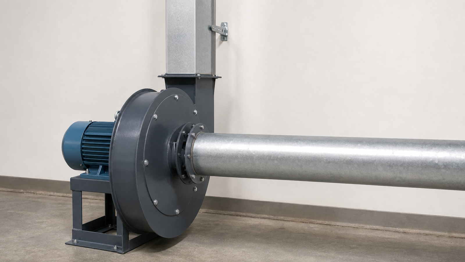
POPULA supports long-duct projects by bringing airflow demand, static pressure, installation space and maintenance requirements into the same selection discussion. For appropriate general industrial applications, the 9-26 high-pressure centrifugal fan provides a product option where the duct route has more resistance than a simple wall or roof exhaust point.
POPULA fan long duct ventilation solution: diagnose resistance before selecting equipment
Every metre of duct, elbow, reducer, tee, damper, hood, grille and filter section adds resistance. A long route with multiple sharp turns can lose far more pressure than teams expect when they focus only on duct length. Poor inlet conditions can make the problem worse: a fan installed too close to a bend, a restricted inlet opening or an undersized connection can create turbulence before air even reaches the impeller. On the discharge side, an unsuitable outlet direction or obstruction can also reduce usable system performance.
A responsible review therefore starts with a duct sketch and operating data. Record the required airflow at each pickup point, duct sizes, straight lengths, fittings, branches, dampers, discharge point, installed fan model, motor speed and any observed vibration or noise. From there, a qualified engineer can estimate system resistance and compare it with the fan performance curve at the intended duty point. This is the basis for determining whether the issue is a duct-layout problem, a control issue, an installation restriction or a genuine need for a different fan.
Why use a 9-26 high-pressure centrifugal fan for multi-bend duct routes
The 9-26 series is designed for forced ventilation and material-transport applications where a system needs higher pressure capability than a low-resistance general-exhaust route. The supplied product range covers a broad selection of airflow and pressure combinations, with larger configurations reaching approximately 79,131 m³/h and 16,014 Pa. Those figures are range limits, not a universal operating point: the final model, rotation, speed, motor and outlet arrangement must be selected from the required airflow and calculated system resistance.
According to the product information, the transported medium must be non-corrosive, non-explosive and non-viscous; it should not contain adhesive material, while dust and grain concentration must remain within the stated limit of 150 mg/m³ and temperature must not exceed 80°C. This makes the series unsuitable for applications that require explosion protection, corrosive-gas handling, sticky media, uncontrolled heavy dust, high-temperature emergency duty or fire-smoke exhaust unless a separately verified product and complete specialist design are used.
How to lay out a long-duct exhaust system more effectively
A better layout does not mean eliminating every bend; site constraints often make that impossible. The aim is to control the resistance that matters most. Keep the main route as direct as practical, use long-radius elbows where space permits, avoid abrupt duct-size changes, and position branches so they do not force one pickup point to take all the available airflow. Dampers or balancing devices should be accessible for commissioning, and inspection doors should be added where buildup or maintenance is expected.
The fan should be installed on a stable base with suitable vibration isolation, supported duct connections and enough space to inspect the inlet, impeller, motor, bearing condition and fasteners. The 9-26 series offers different rotations and outlet-angle arrangements; these should be selected to suit the actual pipe route, not treated as a cosmetic preference. Matching the outlet direction to the duct layout can reduce unnecessary turns directly after the fan and make the installation easier to service.
Commissioning and long-term operating value
After installation, verify airflow at representative end points rather than relying only on the sound or current draw at the fan. Check damper positions, vibration, bearing and motor condition, duct leakage, inlet clearance and whether operating schedules match the process demand. If production lines, collection points or duct branches change later, the resistance calculation and fan duty point should be reviewed again. Long-duct systems are living systems: a modification at one end can change performance at the other.
Solusi ventilasi industri POPULA can support application discussion, 9-26 high-pressure centrifugal fan selection and layout-oriented planning for long duct routes. A practical POPULA fan long duct ventilation solution is built around the whole system—airflow requirement, resistance, fan curve, rotation, outlet direction, installation and maintenance—not simply around choosing the largest available fan.
